Thursday, 31 March 2011

Arsitektur Mikrokontroler MCS-51

Arsitektur mikrokontroler MCS-51 diotaki oleh CPU 8 bit yang terhubung melalui satu jalur bus dengan memori penyimpanan berupa RAM dan ROM serta jalur I/O berupa port bit I/O dan port serial. Selain itu terdapat fasilitas timer/counter internal dan jalur interface address dan data ke memori eksternal.

Blok sistem mikrokontroler MCS-51 adalah sebagai berikut.
ars_mcs51
Salah satu tipe mikrokontroler arsitektur MCS-51 yang banyak digunakan saat ini adalah tipe Atmel 89S51. Tipe ini banyak digunakan karena memiliki fasilitas on-chip flash memory dan In System Programming. Berikut adalah feature-feature untuk mikrokontroler tipe 89S51 buatan Atmel.
4K bytes Flash ROM
128 bytes RAM
4 port @ 8-bit I/O (Input/Output) port
2 buah 16 bit timer
Interface komunikasi serial
64K pengalamatan code (program) memori
64K pengalamatan data memori
Prosesor Boolean (satu bit – satu bit)
210 lokasi bit-addressable
Fasilitas In System Programming (ISP)

MEMORY MAP MIKROKONTROLER MCS-51
map51

PENJELASAN FUNGSI PIN MIKROKONTROLER MCS-51
ic_mcs51
IC mikrokontroler dikemas (packaging) dalam bentuk yang berbeda. Namun pada dasarnya fungsi kaki yang ada pada IC memiliki persamaan. Gambar salah satu bentuk IC seri mikrokontroler MCS-51 dapat dilihat berikut.

Berikut adalah penjelasan fungsi tiap kaki yang biasa ada pada seri mikrokontroler MCS-51.

A. Port 0
Merupakan dual-purpose port (port yang memiliki dua kegunaan). Pada desain yang minimum (sederhana) digunakan sebagai port I/O (Input/Output). Pada desain lebih lanjut pada perancangan dengan memori eksternal digunakan sebagai data dan address yang di-multiplex. Port 0 terdapat pada pin 32-39.

B. Port 1
Merupakan port yang hanya berfungsi sebagai port I/O, kecuali pada IC 89S52 yang menggunakan P1.0 dan P1.1 sebagai input eksternal untuk timer ketiga (T3). Port 1 terdapat pada pin 1-8.

C. Port 2
Merupakan dual-purpose port. Pada desain minimum digunakan sebagai port I/O. Pada desain lebih lanjut digunakan sebagai high byte dari address. Port 2 terdapat pada pin 21-28.

D. Port 3
Merupakan dual-purpose port. Selain sebagai port I/O juga mempunyai fungsi khusus yang ditunjukkan pada tabel berikut.

PIN ( FUNGSI KHUSUS )

P3.0 RXD ( serial input port )
P3.1 TXD ( serial output port )
P3.2 _INT0 ( external interrupt 0 )
P3.3 _INT1 ( external interrupt 1 )
P3.4 T0 ( timer 0 external input )
P3.5 T1 ( timer 1 external input )
P3.6 _WR ( external data memory write strobe )
P3.7 _RD ( external data memory read strobe )

E. PSEN (Program Store Enable)
PSEN adalah kontrol sinyal yang mengijinkan untuk mengakses program (code) memori eksternal. Pin ini dihubungkan ke pin OE (Output Enable) dari EPROM. Sinyal PSEN akan 0 pada tahap fetch (penjemputan) instruksi. PSEN akan selalu bernilai 0 pada pembacaan program memori internal. PSEN terdapat pada pin 29.

F. ALE (Address Latch Enable)
ALE digunakan untuk men-demultiplex address dan data bus. Ketika menggunakan program memori eksternal port 0 akan berfungsi sebagai address dan data bus. Pada setengah paruh pertama memory cycle ALE akan bernilai 1 sehingga mengijinkan penulisan alamat pada register eksternal dan pada setengah paruh berikutnya akan bernilai satu sehingga port 0 dapat digunakan sebagai data bus. ALE terdapat pada pin 30.

G. EA (External Access)
Jika EA diberi masukan 1 maka mikrokontroler menjalankan program memori internal saja. Jika EA diberi masukan 0 (ground) maka mikrokontroler hanya akan menjalankan program memori eksternal (PSEN akan bernilai 0). EA terdapat pada pin 31.

H. RST (Reset)
RST pada pin 9 merupakan pin reset. Jika pada pin ini diberi masukan 1 selama minimal 2 machine cycle maka system akan di-reset dan register-register internal akan berisi nilai default tertentu dan program kembali mengeksekusi dari alamat paling awal.

I. On-Chip Oscillator
Mikrokontroler MCS-51 telah memiliki on-chip oscillator yang dapat bekerja jika di-drive menggunakan kristal. Tambahan kapasitor diperlukan untuk menstabilkan sistem. Nilai kristal yang biasa digunakan pada 89S51/89S52 adalah sekitar 12 MHz, dan maksimum sampai 24 MHz. On-chip oscillator tidak hanya dapat di-drive dengan menggunakan kristal, tapi juga dapat digunakan TTL oscillator.

J. Koneksi Power
Mikrokontroler biasanya beroperasi pada tegangan 3.3 volt atau 5 volt (tergantung serinya). Pin Vcc terdapat pada pin 40 sedangkan Vss (ground) terdapat pada pin 2

source : http://soel.umpo.ac.id/?p=27

Perkembangan Mikrokontroler

Mikrokontroler dan Mikroprosesor

Mikrokontroler adalah keluarga mikroprosesor yaitu sebuah chips yang dapat melakukan pemrosesan data secara digital sesuai dengan perintah bahasa assembly yang diberikan perusahaan pembuatnya. Perbedaan yang mendasar pada keduanya yaitu, mikroprosesor memerlukan perangkat pendukung (RAM, Harddisk, VGA card, keyboard, floppy disk dll) yang dipasang sebagai peripheral eksternal dalam menjalankan instruksi. Mikrokontroler merupakan chip tunggal yang dapat menjalankan instruksi tanpa peripheral pendukung. Meskipun mikrokontroler tidak secerdas mikroprosesor, tapi jika tingkat kepandaian yang dimiliki telah cukup untuk menjalankan tugas dari suatu instrumen, maka mikrokontroler menjadi pilihan pertama karena memiliki kelebihan dalam hal harga, kesederhanaan rangkaian, dan dimensi instrumen yang lebih kecil.

Akhirnya pada masa sekarang penggunaan mikrokontroler telah menjadi tren pada desain teknologi elektronika. Hal ini disebabkan karena teknologi chip mikrokontroler dapat mereduksi sisten digital diskrit dengan digantikan perangkat lunak yang diprogram kemudian diisikan dalam chip tersebut. Mikroprosesor dikembangkan lebih kearah perangkat berbasis komputer sedangkan mikrokontroler lebih banyak ke sistem instrumentasi elektronika.

PERBEDAAN MIKROKONTROLER DENGAN MIKROPROSESOR

Terdapat perbedaan yang signifikan antara mikrokontroler dan mikroprosessor. Perbedaan yang utama antara keduanya dapat dilihat dari dua faktor utama yaitu arsitektur perangkat keras (hardware architecture) dan aplikasi masing-masing.

Ditinjau dari segi arsitekturnya, mikroprosesor hanya merupakan single chip CPU, sedangkan mikrokontroler dalam IC-nya selain CPU juga terdapat device lain yang memungkinkan mikrokontroler berfungsi sebagai suatu single chip computer. Dalam sebuah IC mikrokontroler telah terdapat ROM, RAM, EPROM, serial interface dan paralel interface, timer, interrupt controller, konverter Anlog ke Digital, dan lainnya (tergantung feature yang melengkapi mikrokontroler tersebut).
Sedangkan dari segi aplikasinya, mikroprosessor hanya berfungsi sebagai Central Processing Unit yang menjadi otak komputer, sedangkan mikrokontroller, dalam bentuknya yang mungil, pada umumnya ditujukan untuk melakukan tugas–tugas yang berorientasi kontrol pada rangkaian yang membutuhkan jumlah komponen minimum dan biaya rendah (low cost).


Perkembangan Mikrokontroler
Mikrokontroler MCS-51 keluaran perusahaan semikonduktor Intel, pertama kali dibuat dengan media program EPROM berada di luar chip. Mikrokontroler tersebut adalah periode dari 8031 (generasi pertama). Disamping lebih rumit dan biayanya lebih mahal sistem ini juga memiliki kesulitan dalam mengisi dan menghapus program. Untuk mengisi diperlukan perangkat pengisi khusus dan untuk menghapus diperlukan perangkat lampu ultraviolet dengan spesifikasi khusus pula.

Selanjutnya (generasi kedua) perkembangan teknologi EEPROM yang dapat dihapus dengan kejutan listrik, tetapi sistem ini masih memerlukan perangkat pengisi khusus yang membutuhkan tegangan kerja 12 volt.


Perkembangan selanjutnya (generasi ketiga) adalah mereduksi kerumitan rangkaian dengan dimasukkannya EEPROM ke dalam chips mikrokontroler. Tipe mikrokontroler jenis ini yang dikenal adalah AT89C51, AT89C52, AT89C55 dll.
Semua mikrokontroler tipe-C masih memerlukan perangkat pengisi khusus. Perkembangan terakhir mikrokontroler MCS-51 adalah tipe-S yaitu ISP (in system programeable) dimana EEPROM didalamnya berteknologi flash yang dapat diisi dengan pulsa 5 volt. Sehingga sistem ini dapat diisi dan dihapus langsun dari komputer. Dan perogramannya dapat dilakukan secara on-line dari komputer pada obyek berbasis mikrokontroler yang sedang dikerjakan. Tentu saja hal ini memberikan lebih banyak kemudahan dalam perancangan sistem elektronik


e


Wednesday, 30 March 2011

Hukum Ohm Dan Rangkaian Seri – Paralel

Hukum Ohm menyatakan:

(http://abisabrina.wordpress.com)

“Besarnya kuat arus (I) yang melalui konduktor antara dua titik berbanding lurus dengan beda potensial atautegangan(V) di dua titik tersebut, dan berbanding terbalik dengan hambatan atau resistansi(R) di antara mereka

Dengan kata lain bahwa besar arus listrik (I) yang mengalir melalui sebuah hambatan (R) selalu berbanding lurus dengan beda potensial(V) yang diterapkan kepadanya.

Ilustrasi Hukum Ohm

Ilustrasi Hukum Ohm

Hukum Ohm dikemukakan oleh Georg Simon Ohm, fisikawan dari Jerman pada tahun 1825. Hukum Ohm kemudian dipublikasikan pada tahun 1827 melalui sebuah paper yang berjudul “The Galvanic Circuit Investigated Mathematically“.

Berikut ini contoh penerapan Hukum Ohm untuk menghidupkan lampu LED.

Penerapan Hukum Ohm

Penerapan Hukum Ohm

Menghitung Resistor Seri

Pada rangkaian beberapa resistor yang disusun seri, maka dapat diperoleh nilai resistor totalnya denganmenjumlah semua resistor yang disusun seri tersebut. Hal ini mengacu pada pengertian bahwa nilai kuat arus disemua titik pada rangkaian seri selalu sama.

Rangkaian Resistor Seri

Rangkaian Resistor Seri

Menghitung Resistor Paralel

Pada rangkaian beberapa resistor yang disusun secara paralel, perhitungan nilai resistor totalnya mengacu pada pengertian bahwa besar kuat arus yang masuk ke percabangan sama dengan besar kuat arus yang keluar dari percabangan (I in = I out). Dengan mengacu pada perhitungan Hukum Ohm maka dapat diperoleh rumus sebagai berikut.

Rangkaian Resistor Paralel

Rangkaian Resistor Paralel

Menghitung Kapasitor Seri

Pada rangkaian kapasitor yang disusun seri maka nilai kapasitor totalnya diperoleh dengan perhitungan berikut.

Rangkaian Kapasitor Seri

Rangkaian Kapasitor Seri

Menghitung Kapasitor Paralel

Pada rangkaian beberapa kapasitor yang disusun secara paralel maka nilai kapasitor totalnya adalah penjumlahan dari semua nilai kapasitor yang disusun paralel tersebut.

Rangkaian Kapasitor Paralel

Rangkaian Kapasitor Paralel

Cara Mudah Membaca Gelang Warna Resistor

Lazimnya gelang resistor terdapat 4 gelang kode yang umumnya digunakan untuk presisi rendah dengan toleransi 5%, 10% dan 20%. Gelang pertama dan kedua mewakili angka resistor. Gelang ketiga mengindikasi perkalian (multiplier) berapa ‘nol’ yang ditambahkan. Jika multiplier band adalah emas (gold) atau perak (silver) kemudian desimal digeser ke kiri satu atau dua (dibagi dengan 10 or 100). Gelang toleransi (tolerance band) deviasi dari nilai spesifik, biasanya terdapat jarak dari gelang lain.

Sebagai contoh, untuk resistor dengan nilai 560 ohm, 5% maka gelang warnanya adalah hijau, biru, coklat dan emas. Penjelasan: Hijau dan biru mewakili angka (56); sedangkan coklat adalah pengali (multiplier) (10) dan emas adalah toleransi (5%). Sedemikian sehingga nilainya 56*10 = 560.

Resitor dengan 5 gelang: Resistor dengan gelang seperti ini digunakan untuk rangkaian elektronika dengan presisi tinggi, resistor dengan presisi 2%, 1% atau bertoleransi lebih rendah. Cara membaca gelang mirip dengan sistem sebelumnya (4 gelang); hanya saja ada perbedaan nomor dari angka. Gelang pertama, kedua dan ketiga mewakili nilai angka, gelang ke empat adalah pengali (multiplier) dan gelang ke lima adalah toleransi.

Jika gelang ke tiga diubah ke warna merah, maka pengali (multiplier) akan menjadi 100, sehingga nilainya 56×100 = 5600 ohms = 5.6 k ohms. Jika gelang pengali (multiplier band) adalah emas atau perak, kemudian desimal poin akan digeser ke kiri satu atau dua tempat (dibagi dengan 10 atau 100). Sebagai contoh, sebuah resistor dengan gelang hijau, biru, perak dan emas mempunyai nilai 56*0.01 = 0.56.
Catatan: 20% resistors hanya mempunyai 3 gelang – artinya, gelang toleransi (gelang ke empat tanpa warna).

Standarisasi warna


Warna

Gelang ke-1

Gelang ke-2

Gelang ke-3 *

Pengali

Toleransi

Koefisien Suhu

Fail Rate

Hitam

0

0

0

×100

Coklat

1

1

1

×101

±1% (F)

100 ppm/K

1%

Merah

2

2

2

×102

±2% (G)

50 ppm/K

0.1%

Jingga

3

3

3

×103

15 ppm/K

0.01%

Kuning

4

4

4

×104

25 ppm/K

0.001%

Hijau

5

5

5

×105

±0.5% (D)

Biru

6

6

6

×106

±0.25%(C)

Ungu

7

7

7

×107

±0.1% (B)

Abu-abu

8

8

8

×108

±0.05% (A)

Putih

9

9

9

×109

Emas

×0.1

±5% (J)

Perak

×0.01

±10% (K)

Tanpa Warna

±20% (M)

* Gelang ke-3 hanya untuk 5-band resistors (source: http://pinginpintar.com/?p=236)


Tutorial Electronic Workbench 3

The oscilloscope

An oscilloscope is a far more powerful instrument than a bargraph indicator or even a voltmeter. It can show you the time dependence of the signals in your circuit. The EWB oscilloscope provides a fairly close approximation of a real one. It has two independent input channels, A and B, an input for an external trigger and a ground connection.
Figure 3. The EWB oscilloscope icon with its terminals.

To look at the output of your signal generator you can add anoscilloscope to the circuit you just made.

1. Drag the oscilloscope onto the circuit window, and double-click on it.The oscilloscope has four terminals, for two independent input channels, a trigger input and a ground connection. The input channels sense voltages with respect to ground! As long as there is at least one ground terminal attached to your circuit, it is not necessary to connect the oscilloscope ground. We will discuss the issue of how the oscilloscope is triggered in class. At this point, leave the triggering
on auto.

2. Connect channel A to the "+" output of the function generator, and
activate the circuit. You should now have a sine wave on your oscilloscope screen.

3. Make drastic changes in the signal amplitude and frequency, andadjust the sensitivity and time base settings such that you still maintain an easily interpretable picture of the wave form on the oscilloscope screen. It may be necessary to occasionally reactivate the simulation.
Figure 4. Using the oscilloscope to investigate the signals from the
function.

4. Change the offset on the function generator to a value of the order of
the amplitude. This adds a constant voltage to the signal. You will see
the trace on the oscilloscope move up (or down). You have two options
to move it back to center.
8

5. Change the "y position" such that the trace comes back on center.
This can always been done as long as the offset is not too large. (Most
oscilloscopes cannot produce an internal offset that is much larger
than the full scale display range.)
6. Change the "y-position" back to zero, and select "AC" as input
coupling mode. In this mode the DC component of the signal is
removed. The EWB oscilloscope is very good at this, but real
instruments have a difficulty distinguishing between DC and very
slowly oscillating signals. In practice, avoid the AC input mode for
signal frequencies less than 100 Hz.
To get a larger image of the oscilloscope, try the expand button. On the
expanded display you will find two vertical line cursors. By moving these
around you can measure time and amplitude of points on the displayed
traces.

Electronic WorkBench tutorial 2


Using the main instruments

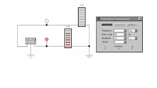
EWB incorporates a number of instruments, such as an oscilloscope and a function generator. The following provides an introduction to these two instruments. To briefly investigate the function generator, build the circuit below.
Figure 2. The function generator with bargraph displays.

The function generator

1. Drag the function generator onto the circuit window.
2. Double-click on the function generator. You can now change its settings, such as the wave form, the signal amplitude and the signal frequency.
3. The function generator has three terminals, "-", "common" and "+". Connect the common to a ground terminal.
4. Get two red probes from the Indicators toolbar. Wire them to the "+" and "-" terminals, and activate the circuit. You should now have two blinking red lights. To get a little bit more information we will attach a second kind of indicators.

5. Get two decoded bargraph displays form the indicator toolbar.
6. Wire one terminal of each of the bargraph indicators to ground, and the other terminals to the "+" and "-" terminals of the function generator.
7. Experiment with changing the wave form and frequency of the signal generator.


Electronic WorkBench tutorial


Introduction


Electronic WorkBench (EWB) is a simulation package for electronic circuits. It allows you to design and analyze circuits without using breadboards, real components or actual instruments. EWB's click-anddrag operations make editing a cir
cuit fast and easy. You can change parameters and circuit components on the fly, which make "what-if" analysis straight foreward.

This tutorial is intended as a quick introduction to E
WB's basic features. It first leads you through the fundamental steps of putting a circuit together and analyzing its function using the instruments. The final part of the tutorial consists of two exercises that try to illustrate the
power of EWB. It also tries to encourage you to apply the "what if" approach to circuit design. It will greatly help your understanding of electronics
if you use EWB in an interactive manner: Make change to the circuits you are working on, observe the effects that these changes have,
and try to understand them. EWB puts very little constraints on parameters so do not be too timid, don't just change things by 10%, try out what happens when you change them by a couple of orders in magnitude.

Directly printing EWB schematics and graphs does usually not produce satisfactory result, and leads to a tremendous waste of paper. It is bette
r to incorporate EWB results by copying them to the clipboard using the copy as bitmap command, and then pasting this into a something like a word document.


Directly printing EWB schematics and graphs does usually not produce satisfactory result, and leads to a tremendous waste of paper. It is better to incorporate EWB results by copying them to the clipboard using the copy as bitmap command, and then pasting this into a
something like a word document.

To open EWB click on its icon. Initially you will see an empty circuit window and two toolbars, the circuit toolbar with the common file ma
nagement, editing and graphics tools, and a Parts Bin toolbar from which you can select a wide range of circuit elements, and instruments. The following will guide you on your first attempt to simulate circuits.

Building and testing a circuit

In this part of the tutorial, you will build the simple DC voltage divider circuit shown below.
Figure 1. A resistive voltage divider

Step 1. Place the components on the circuit window

To build the circuit, you need a battery, two resistors and a ground connection. Assemble the components for the circuit.

1. Choose File/New to open a new circuit file.
2. Click in the Parts Bin toolbar. The basic toolbar should appear.
3. Drag two resistors from the toolbar to the circuit window.

To keep the Basics toolbar open, drag it onto the circuit window. Otherwise, it will close after you drag an item from it, and you will have to reopen it for every resistor.

4. Move to the Sources on the Parts Bin toolbar. Click on it and a toolbar containing the battery and ground should appear. Drag those onto the circuit window.

Step 2. Arranging the circuit elements

You can change the orientation of the circuit elements either by rotating them or flipping them over. To do this, select the circuit element and either click on the standard rotated/flip icons on the toolbar, or select the desired operation under Circuit. In this case you want to rotate both resistors.

1. Select both by either CTRL+click, or by dragging the mouse over them.
2. Choose your favorite way to rotate by 90 degrees.

Note that selected circuit elements are highlighted/changed color.

Step 3. Wire the components together

Most components have short lines pointing outwards, the terminals. To wire the components together you have to create wires between the components.

1. Move the pointer to the terminal on the top of the battery. When you are at the right position to make a connection, a black dot appears. Now drag the wire to the top of the upper resistor. Again a black dot appears, and the wire snaps into position.
2. Wire the rest of the components in a similar manner. You should end up with something like this:

Initially you wiring may not look very pretty. However, after making the connections, you can move wires and components around without breaking the connections.

Step 4. Set values for the components

Initially, each component comes up with a pre-set, default value, e.g., the battery voltage is set to 12 V. You can change all component values to suit your application.

1. Double-click on the component.
2. Select VALUE
3. Change its value.
4. Click OK.

Step 5. Save your circuit

Save your work frequently!

1. Select File/Save.
2. Proceed in the normal way for saving files.

Step 6. Attach the voltmeter

To measure voltages in your circuit you can use one or more voltmeters.

1. Drag a voltmeter from the indicator toolbar to the circuit window.
2. Drag wires from the voltmeter terminals to point in your circuit between which you want to measure the voltage.
3. Activate the circuit the circuit by clicking the power switch at the top right corner of the EWB window.

Step 7. Make changes and additions

You now have a very simple but functioning circuit. Take this opportunity to make some changes and additions.

1. Add an ammeter to the circuit to measure the current through the resistors.
2. Change the values of the resistors, and observe the change in the currents and voltages.

The ammeter can be connected by positioning it on top of the wire through which you want to measure the current. EWB will automatically make the right connections. If you are not sure that this is done correctly, drag the ammeter, the wires should move with it.

Note that the ground connection plays no particular role in this measurement. The voltmeter is not connected to a reference point. It functions very much like the hand-held multimeter in the lab. You can measure voltage differences between any pair of points in the circuit.